Showing posts with label qrp. Show all posts

Tuesday, September 22, 2020

CWOPs in the Texas QSO Party


The TQP is my favorite 'big' contest each year. While doing my usual CW-QRP thing this month, I kept noticing that during a lot of QSOs, a name would pop into my head though not part of the exchange: Sam, Van, Marv, Chuck, Hank, John (lots of those), Claude and so on. I realized that they were familiar from the CWTs that I enjoy on Wednesdays. There were so many that I became curious about how many CWOPs I was working.

At first I thought it would take a little programing to answer the question but, at least in Linux, it was actually pretty easy.

First I went to the CWOPs website, found the member roster and downloaded a spreadsheet file with all the member calls listed. From that spreadsheet I copied only the calls (well over 2000 currently) to a file: CWOPs_members.txt - one call per line

Then I used a similar process on my TQP log but removed the dupes (for example I worked VE3NNT on 2 bands) before copying that data to another file: TQP_2020_uniques.txt - again one call per line

I used the Linux command grep to look at leach line in the first file and check for a match in the second file with output to Matches.txt:

grep -oFf CWOPs_members.txt TQP_2020_uniques.txt > Matches.txt

If I had only wanted a count, I could have used:

grep -oFf CWOPs_members.txt TQP_2020_uniques.txt | wc -l

I found that slightly over 46% of the contacts I made in the TQP were with CWOPs members. More than I thought. Almost half.

My thanks to each and every one of them. 


cln – Nick
WB5BKL
'599 BURN'


Thursday, August 6, 2020

An Omni-Angle Antenna for 6M

A while back, several posts on the CWOPS reflector caught my attention.  They mentioned openings on 6M during the weekly CWOPS Mini-tests.   That reminded me that my K3/10 has both 6M capability and a suitable preamp for that band. 

I am not ready to replace my rotatable antenna (a 2-element delta loop for 10 and 15M), so I looked for sometiing simpler but ideally omni-directional.  I settled on the Omni-Angle for 6M from PAR Antennas, as it seemed well constructed, got good reviews and was not too expensive.

Assembly was straight forward.  PAR Antennas has a video available which helped me with adjusting the antenna 'match'.  Since it was so small and lightweight, I elected to put it stepladder height on the tower and give it a try.  Here is an image:

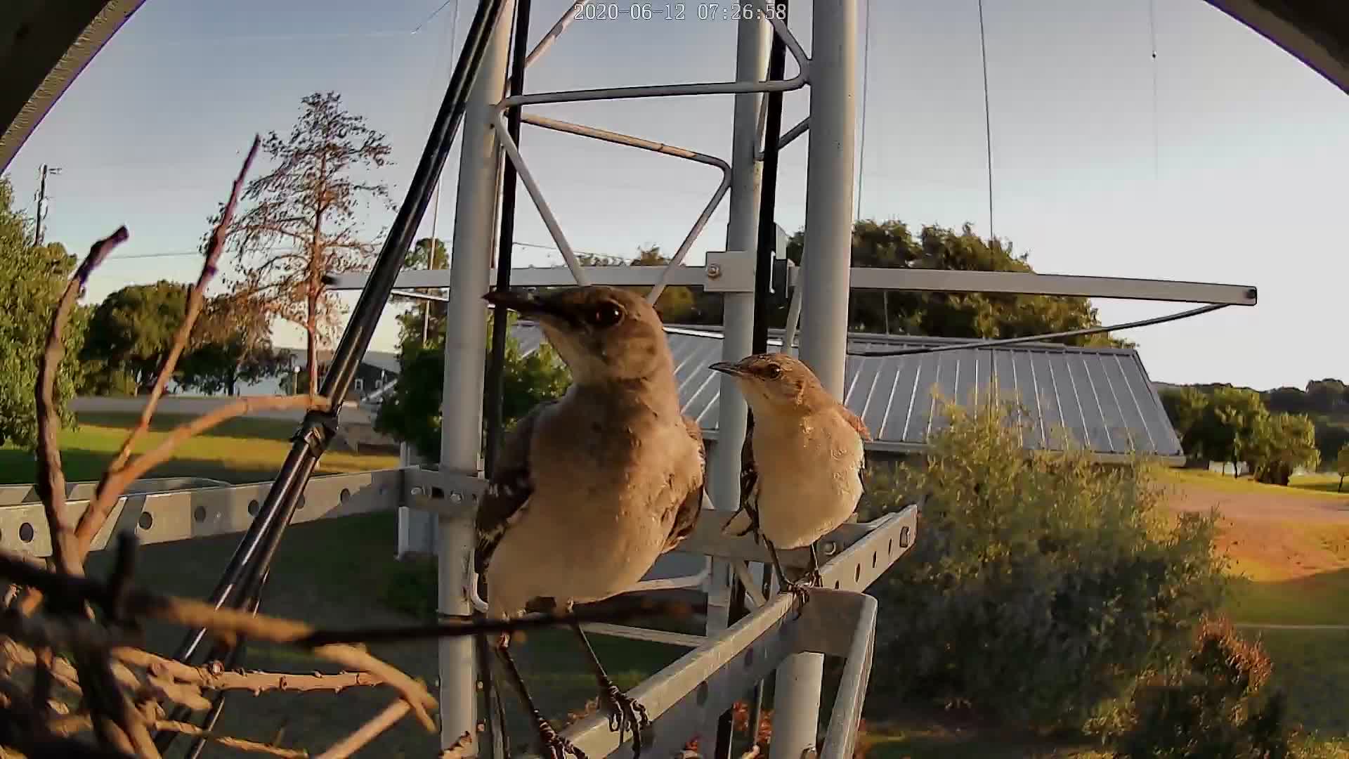
And below is another image from the rear.  Mom and Pop Mockingbird were building a nest between the Omni-Angle and the tower brace.  I can imagine them saying, "There goes the neighborhood!"

Dustin, much younger than WB5BKL, climbs for me.  Here is an image of him, several weeks later,  almost done with mounting the Omni-Angle at my designated height.  Dustin reported that there were three eggs in the mockingbird nest.  We tried not to disturb them.


So far, I am very pleased. I used my FA-VA-4 antenna analyzer to adjust resonance to 50.090 MHz at stepladder height and Dustin made very slight changes when it was up in the air.  (Note that the camera was tilted, not the tower.  😉)

I made a couple of contacts with the antenna at stepladder height and then had fun in the ARRL VHF - making 8 contacts in very casual operation with the antenna up in the clear.

At 5W of course.  QRP CW.

Now  I watch 6M for openings!


cln
WB5BKL


Wednesday, February 13, 2019

160M 1:2.25 Impedance Transformer

In order to try out 160M, I put up an inverted "L" and adjusted the length to resonance using an antenna analyzer (FA-VA4).  My frequency of choice was 1810 KHz - to match my QRP interests.

At this writing, I have 12 radials at the base, with various lengths of 15 to 40 feet over very rocky soil (granite, gneiss).

I did no modeling - just threw up some wire that fit my physical situation.  Impedance at resonance was around 24 Ohms.

I wound a test transformer on an old toroid of unknown characteristics just to see if I could get close to a 50 Ohms match.  That was successful and I even made several contacts at QRP levels.

I decided to wind a better (and I hope, more efficient) version.  I used a FT-150A-K core from  Amidon along with 10 feet of AWG#14 HAPT wire and some glass cloth tape.  The transformer I chose was the W2FMI-2.25:1-HU50 from the Amidon Transmission Line Transformers Handbook on the Amidon website.  this is a Jerry Sevick design.  I am, of course, using it 'backwards'...

To the right is the toroid as wound.  Sevick notes that the #14 takes some effort to wind and suggests leaving long leads on each end for leverage.  Good advice.

The image below shows (unclearly - sorry) the connections before soldering.

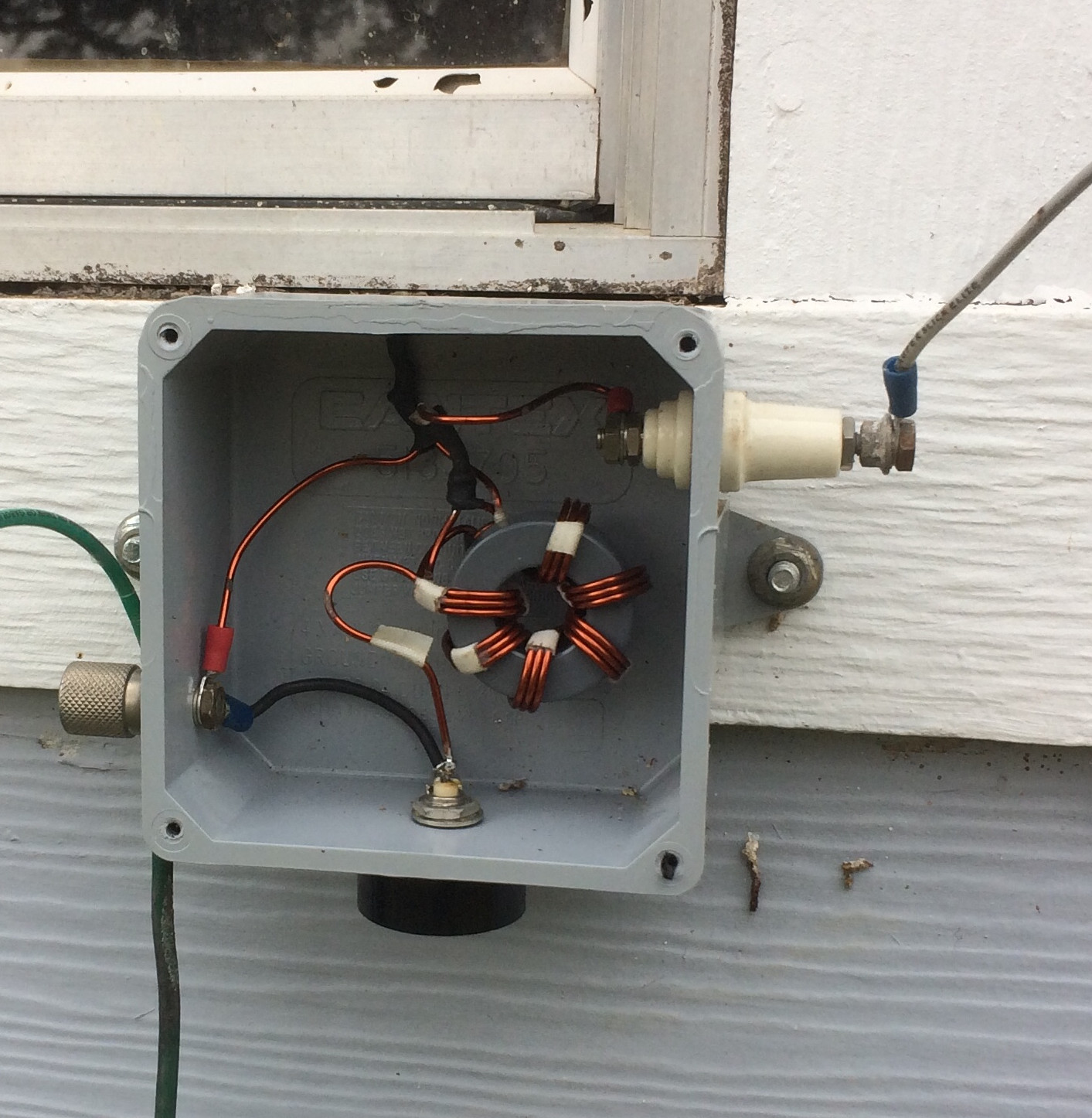
And here is the wired version with the "proof of concept " un-un to the left.  The box is an outdoor junction box (with water-sealed lid, not shown) that I picked up at a local big-box store.  Pretty handy.


And here it is as installed.  The BNC feed to the shack is at the bottom, the inverted "L" connects to the right and the ground and radials to the left.

So far, I am very pleased to get something cheap and easy working for 160M.  This might not be the best antenna, but for my circumstance it is up and working.   At 1810KHz, the antenna presents a SWR of about 1:1.1, rising quickly away from that QRP frequency.

I do appreciate Mr. Sevick's work. 

Now for more radials!

cln - Nick
WB5BKL
Lake Buchanan


Sunday, November 25, 2018

A Grand Day Out - QRP Portable

With apologies to Wallace and Gromit.

I was able to operate portable four times this year.  Briefly, here are some photos and comments.

Texas State Parks on the Air (TSPOTA)

I operated only on Saturday - April 7th.  As it was cool (~39F), damp and threatening rain, I elected to operate while sitting in the car at Longhorn Cavern State Park (EM00tq).  I only made 15 QSOs  No other Texas state parks were heard.  As of this writing, no scores have been posted.  Used the K1 @ 5W with a 20M dipole.  This is a pleasant and scenic location, and my closest state park.


QRP to the Field (QRPTTF)

Two weeks after the TSPOTA event, I was out again - this time at Black Rock Park in Llano County (EM00ss).  More on Black Rock Park later.  Rig was again the K1 and this time I hung a 40M EFHW in addition to the 20M dipole.  25 QSOs was good enough to get me into the top five..  Got to meet a dog named Gussie.  She was interested in my stash of Ritz crackers.


The Flight of the Bumblebees (FotBBs)

This was on the 29th of July and again at Black Rock Park.  I made 29 QSOs and had another good time.  It was very warm and lots of folks were enjoying the park.  Same rig as above.


The Skeeter Hunt

This was on the 29th of August and once more at Black Rock Park.  Again 29 QSOs with the K1 @ 5W, the 20M dipole and the 40M EFHW.


More on Black Rock Park

This park, on the west side of Lake Buchanan, is operated by the Lower Colorado River Authority (LCRA).  This is not a state park, but is operated in a similar manner.  In my experience, these parks are very popular with families, especially in the summertime.  I would strongly suggest reservations or getting there early and being flexible.  Here are some links:

LCRA

Black Rock Park

I had a very good experience at this park.  The staff was both friendly and very helpful.  I did a scouting run through the park early in 2018 and made note of the sites with 20 and 40M spaced trees.  :-)   No one seemed to have any problem with me hanging antennas - and on my last visit, I was greeted with, "Oh, you're that radio guy."


cln - Nick
WB5BKL


Monday, October 22, 2018

QCX - 30M Transceiver - Mods

Two more mods for my 30M QCX.

I have already completed several mods, as detailed in QCX - 30M Transceiver .  The final one I did last year was intended to increase the power output, but was only marginally successful.

Recently, I purchased a 20M QCX, but after finishing construction, I found that the ATmega328P microprocessor was not working.  Hans, at QRPLabs, had seen this problem before and was happy to send a replacement - and I ordered an additional latest firmware chip for this 30M rig.  While waiting on the replacements to arrive, I elected to replace the capacitors in the low-pass output filter.

I replaced C25 and C26 with 560pF silver micas and replaced C27 and C28 with 270pF silver micas.

These capacitors were huge compared to the originals - so I had to get creative in placing them.


I


Note that C27 and C28 had to move to the bottom of the PCB - and were tilted slightly to provide clearance for the enclosure.


I am fortunate to have a low-priced but effective solder-sucker that I bought some years ago.  This would have much, much more difficult without it.

Here are the parts I removed.  The largest is about the size of the head of a kitchen match.  I used silver micas as I had the correct values for the 30M QCX on hand.


Just as I was completing this modification, the replacement microcontrollers from QRPLabs arrived - with firmware version 1.00f.

The only volatile information that I wanted to keep was the correction for the 27MHz frequency reference (Entry 8.5:  27.004.550), so I made a note of that and replaced the 1.00b firmware with 1.00f.  As expected, no re-alignment was really needed, but I touched it up anyway.

After all these changes, I now have 3.4W out measured with the same equipment as earlier.  This is just about what the designer predicts, given my 12.4V motorcycle battery power supply and the polarity protection diode.

I am pleased and will call this good for now.

My thanks to W5IQS for suggesting mounting the capacitors on the bottom of the PCB.   And to Hans, of course.  The more I use this little rig, the more I like it.

Here is an image of the 30M QCX in its new enclosure.


cln - Nick
WB5BKL


Sunday, December 3, 2017

QCX - 30M Transceiver

Recently, I built a QRPLabs QCX, the 30M version.  I have stopped recommending anything to anyone, but I hope to build both the 40M and the 20M versions in the near future.  I have collected a few hints, in no particular order:

Hints:

*  There is a impressive video of a QCX build here by IZ7VHF.  Worth a look if you are considering the QCX.

*   The local big-box office supply store wanted more than the list price of the QCX to print a color manual - even just B/W was more than Hans charges for the kit plus shipping.  I put the manual on an old iPad and propped it up near my work area.  I only printed the inventory pages, the section concerned with winding of T1 and the Cheat Sheet near the end of the manual.  I had the Cheat Sheet laminated.

*   If you use something like an iPad or PC to display the manual, all the illustrations can be handily expanded.

*   I used a pair of binocular magnifying glasses.  Also very handy.

*   I would strongly advise a complete inventory of all parts (also see below).  I had one extra capacitor.

*   I would also strongly advise organizing - at an absolute minimum - the capacitors and resistors by value.  Muffin tins would be nice (and would only take moments to wash and slip back into the kitchen).  If you are fortunate enough to have a workplace that will remain undisturbed, at least draw circles for each value on a piece of cardboard and stick them in that.

*   All of my placement errors were with the resistors.  I strongly advise the hint above, and re-checking the color codes against each other and the inventory listings.  Use a VOM to resolve problems with color resolution.  Slight color (colour?) blindness runs in my family.

*   With my tired, old eyes, I found it hard to count the turns on T1.  I ended up taking a photo with my phone, transferring it to my PC and enlarging it on-screen.  I had one turn too many on the S3 winding.

*   When you cut the small connectors apart, I would strongly advise covering the connector and tool with a cloth.  My first cut ricocheted off the wall, then the bookcase then my chest.  Miraculously, I found it in the work area after an extensive search of the floor.  Of course, use eye protection.

*   Take Hans' suggestion and orient all the parts either the same way or at least in such a fashion that the values can be read later.  Remember that this project will be very crowded at the end.


*   The page breaks in the manual are occasionally unfortunate.  Be extra careful when the instructions and the illustration are on different pages.  As mentioned earlier, the illustrations in the Manual I downloaded to my iPad can be enlarged when clicked.

*   From my experience with SMT projects, I now have a large, cheap aluminum foil cookie sheet with a properly sized piece of white cotton cloth taped inside.  Very handy.  If you ground it, even better.


Finished:

First impressions - the receiver is HOT!  I am impressed.  The QCX seems to hear almost everything my K3 does.  


Power output was low - measured externally at about 1.4W.  

I spent some time reading the QRPLabs e-mail reflector and then followed Hans Summers' recommendations for mods to the QCX.


Mods:

Here is a listing of the modifications I made.

Before and after each change, I made a series of measurements.  First was a 5 second key-down followed by a 15 second rest, then repeated twice more.  Then a 30 second key-down, followed by a 1 minute rest , then repeated twice more.  I am reporting averages of these measurements.  Power was measured independently of the QCX with a 20W Elecraft 50 Ohm dummy load.  I also recorded the supply potential.

I did the mods in two stages, mostly because the changes to L1, L2 and L3 were a little tedious.

Mod #1        -   12.55V supply
    Before:      5s      1.55W
                30s      1.69W
    ** Removed 1 turn from L1, L2, and L3
    After:       5s      1.36W
                30s      1.38W
    ** Re-alignment
    After        5s      1.56W
                30s      1.52W 

Mods #2&3&4   -   12.38V supply
    Before       5s      1.4W
                30s      1.5W
    **Install 1N5819 Schottky diode
    After        5s      1.5W
                30s      1.6W
    **Install 10K resistor from Q5 drain to +12V
    After        5s      1.4W
                30s      1.6W
    **Replace MPS 2907 with MPS751
    After        5s      1.5W
                30s      1.6W


    **Re-alignment
    After        5s      2.0W
                30s      2.0W


The image below shows the diode and resistor addition to the bottom of the PCB.


I think (but do not know) that the removal of one turn from the low-pass filter did not do much.  I think the addition of the 10K Ohm resistor and the change to the MPS751 did a little good.

At this writing, I am satisfied enough that I will await more information from the designer before diving into the circuit board again.  

As it stands, 2W seems to do well on 30M given reasonable propagation.  The Reverse Beacon Network seems to hear me just fine.

More to come, I hope.


cln - Nick
WB5BKL


Friday, December 1, 2017

Ham Gadgets Ultra PicoKeyer

I have been using the AA0ZZ EZKeyer II for several years (see my earlier post).  It has worked well with my K1, which I typically use portable.  There are shortcomings, however:  No easy speed control and only 3 memories. 

I tried a keyer with 8 memories, but had so many problems with missing, broken or incorrect parts, odd i/o design and sporadic support that I gave up - sadder but wi$er.

 Then I found the Ham Gadgets Ultra PicoKeyer.
 

The price was right - and I could even chose a color!  Woo-hoo!  

The construction was pretty easy (and the manual is very good).  It was ready to go in under two hours (I work very slowly).

I hooked it up to the Elecraft K1, switched the K1 to 'straight key' mode and gave it a try...

Semi-gibberish.

After several tries and careful inspection - to no conclusion - I decided to give it a try with my K2.  Again semi-gibberish. 

More experiments and some searching of the Elecraft e-mail list archives suggested that the 'ring' connection was live. 

Note:  Elecraft requires a 1/8" three-conductor (stereo) plug for CW input to their K1 and K2 transceivers.  If used in straight key mode, nothing can be connected to the 'ring', just the tip and the shell.  Straight Key mode allows control by an external keyer.

I sacrificed a cable and opened the 'ring' wire.  Everything worked just fine!   How odd.

Then I decided to take a very close look at the PCB for potential shorts.  None found, but there was a PCB connection to the 'collar' pin on the output jack.  It was NOT on the schematic, but it's there:


Since it seemed to be the cause of the problem, I cut that trace.  Success! 

Everything worked normally for both the K1 and the K2. 

I did communicate my findings with Ham Gadgets, but I am not sure they fully understood the issue when the PicoKeyer was used with these Elecraft rigs. 

Hence, this entry.

I filled in the embossing on the front of the keyer.  Looks nice.


This is a neat little keyer.

cln - Nick
WB5BKL

Wednesday, August 9, 2017

The Hendricks DC30B Resurrection


Recently I found a partially completed Hendricks DC30B 30M transceiver kit on eBay. It is small - a bit larger than a pack of playing cards.  The transceiver is direct conversion, crystal-locked and CW only.  Below is the eBay posting image:

 
The partial kit was advertised as “incomplete, not working and/or for parts”. The image reveals some of the missing parts, Q1 (the final), a toroidal transformer, one capacitor, the case top, etc. For some reason the 78L05 voltage regulator had been removed and replaced but not soldered. I ordered about $5 worth of parts (including the suspect 78L05).

While waiting on the parts, I very carefully went over the construction and found one electrolytic installed backwards. Otherwise, I thought the build quality good.

I wonder why it was abandoned...


Once the missing parts arrived, I followed the extensive assembly instructions available on the web and – to my pleasant surprise, it fired right up. Here's the testing lash-up.


I found a fine resource in the Yahoo DC40Kits email group. I got good advice and welcome encouragement both on and off-list.

 
After testing, I completed the installation in the supplied clamshell chassis half. Unfortunately I could not locate the top – and have yet to find a suitable replacement.

Output was right at 1 Watt with a nice 12.6V supply. I called CQ a lot until I made my first QSO with NK8O in Kansas (image to the left). The antenna was a 30M sloper and Chas gave me a 579. I have since had better luck when 30M was in good shape, usually at night.  (Note:  The K3 was on - but not in use)


Some thoughts:

This was a lot of fun for the price of a couple of fancy coffees for the better half and me. My biggest mistake was to limit myself to the supplied case. I have since learned of several mods which I could have applied easily. My second mistake was to not mount a socket for the crystal. The supplied Xtal (10.120KHz) is nowhere near the usual QRP frequencies.  Personally, I consider the keyer IC WB5BKL-unfriendly.  I have also read of a few design deficiencies – which have not bothered me.

All in all, a fun project.

cln – Nick
WB5BKL

Sunday, August 16, 2015

2015 Skeeter Hunt

The New Jersey QRP Club's Skeeter Hunt will be the last QRP field event for me this summer.  Here's a photo at my favorite spot in Longhorn Cavern State Park:

My score this year was not as good as in previous outings (I will blame it on propagation), but I did have a good time - as usual.  Also, temperatures were not as hot as in previous years - it only reached around 104F - but there was a breeze most of the time and I had nice shade from two cedar trees.
This year - just for fun - I tried my first video:  Click here.


Since I run Linux, I used 'Openshot'.  After a couple of tutorials on the web and a couple of misfires, I got the basic concepts and I had a lot of fun working on it.  

This year had a couple of other firsts - I visited with my first park ranger/employee (this location is quite a ways from the main park area) and explained how I managed the antennas (a fishing pole, 7-pound-test line and a brightly colored sinker along with nylon twine).  And, yes, they went up and down each visit.

Also, I found this, which was interesting.  This area is moderately popular for its view of the Colorado River, Kingsland (the closest town) and Packsaddle Mountain (SOTA:  W5T/EF-003).  Not too bad a location for that purpose, I guess.  Not exactly my first choice, but as my old friend Murel used to say, "That's why there are red cars and green cars and blue cars..."

My thanks to the NJQRP Club and to W2LJ (the organizer - who I actually worked!).

Had fun.

WB5BKL - Nick