Showing posts with label antenna. Show all posts

Thursday, August 6, 2020

An Omni-Angle Antenna for 6M

A while back, several posts on the CWOPS reflector caught my attention.  They mentioned openings on 6M during the weekly CWOPS Mini-tests.   That reminded me that my K3/10 has both 6M capability and a suitable preamp for that band. 

I am not ready to replace my rotatable antenna (a 2-element delta loop for 10 and 15M), so I looked for sometiing simpler but ideally omni-directional.  I settled on the Omni-Angle for 6M from PAR Antennas, as it seemed well constructed, got good reviews and was not too expensive.

Assembly was straight forward.  PAR Antennas has a video available which helped me with adjusting the antenna 'match'.  Since it was so small and lightweight, I elected to put it stepladder height on the tower and give it a try.  Here is an image:

And below is another image from the rear.  Mom and Pop Mockingbird were building a nest between the Omni-Angle and the tower brace.  I can imagine them saying, "There goes the neighborhood!"
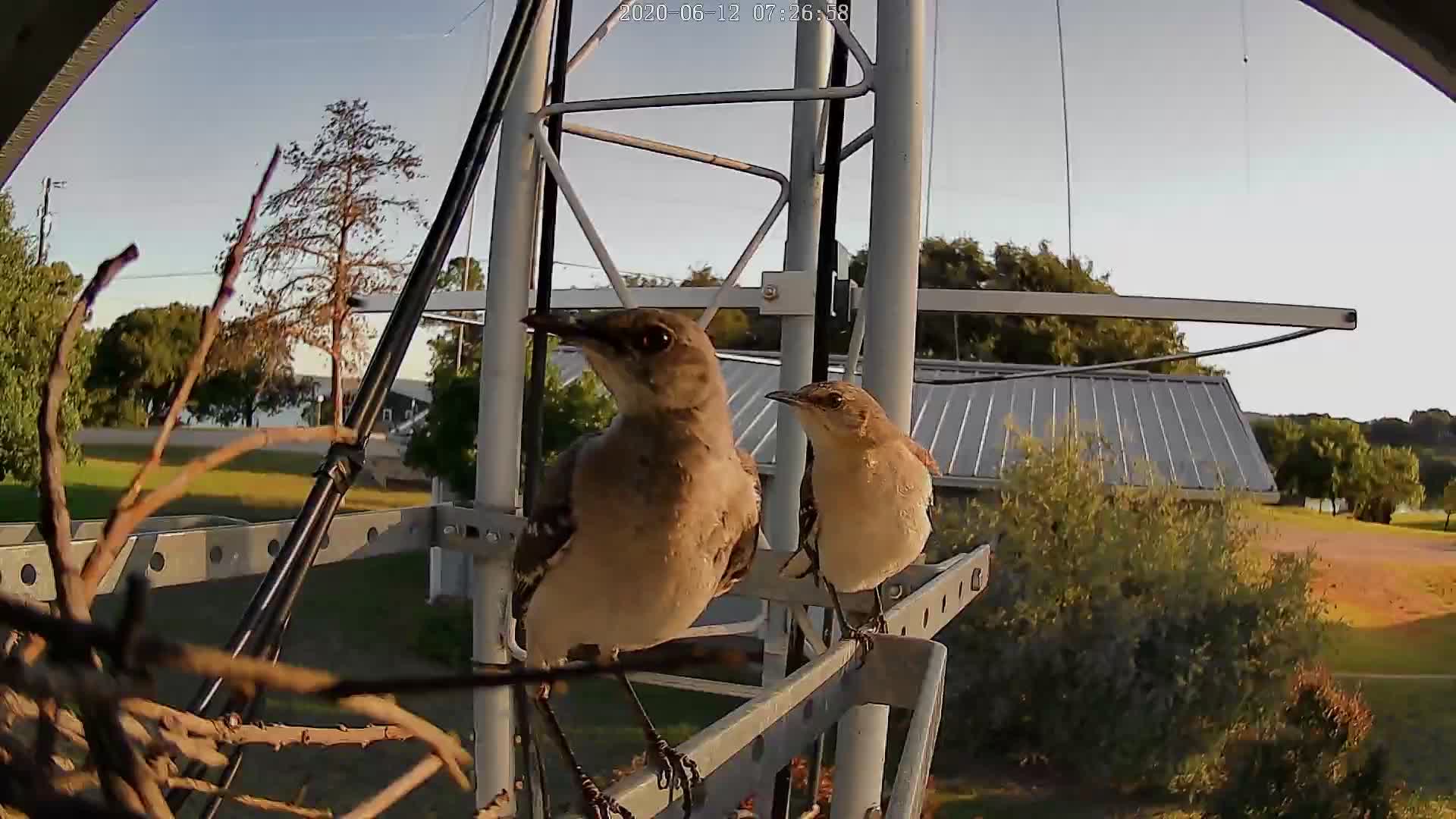
Dustin, much younger than WB5BKL, climbs for me.  Here is an image of him, several weeks later,  almost done with mounting the Omni-Angle at my designated height.  Dustin reported that there were three eggs in the mockingbird nest.  We tried not to disturb them.


So far, I am very pleased. I used my FA-VA-4 antenna analyzer to adjust resonance to 50.090 MHz at stepladder height and Dustin made very slight changes when it was up in the air.  (Note that the camera was tilted, not the tower.  😉)

I made a couple of contacts with the antenna at stepladder height and then had fun in the ARRL VHF - making 8 contacts in very casual operation with the antenna up in the clear.

At 5W of course.  QRP CW.

Now  I watch 6M for openings!


cln
WB5BKL


Wednesday, February 13, 2019

160M 1:2.25 Impedance Transformer

In order to try out 160M, I put up an inverted "L" and adjusted the length to resonance using an antenna analyzer (FA-VA4).  My frequency of choice was 1810 KHz - to match my QRP interests.

At this writing, I have 12 radials at the base, with various lengths of 15 to 40 feet over very rocky soil (granite, gneiss).

I did no modeling - just threw up some wire that fit my physical situation.  Impedance at resonance was around 24 Ohms.

I wound a test transformer on an old toroid of unknown characteristics just to see if I could get close to a 50 Ohms match.  That was successful and I even made several contacts at QRP levels.

I decided to wind a better (and I hope, more efficient) version.  I used a FT-150A-K core from  Amidon along with 10 feet of AWG#14 HAPT wire and some glass cloth tape.  The transformer I chose was the W2FMI-2.25:1-HU50 from the Amidon Transmission Line Transformers Handbook on the Amidon website.  this is a Jerry Sevick design.  I am, of course, using it 'backwards'...

To the right is the toroid as wound.  Sevick notes that the #14 takes some effort to wind and suggests leaving long leads on each end for leverage.  Good advice.

The image below shows (unclearly - sorry) the connections before soldering.

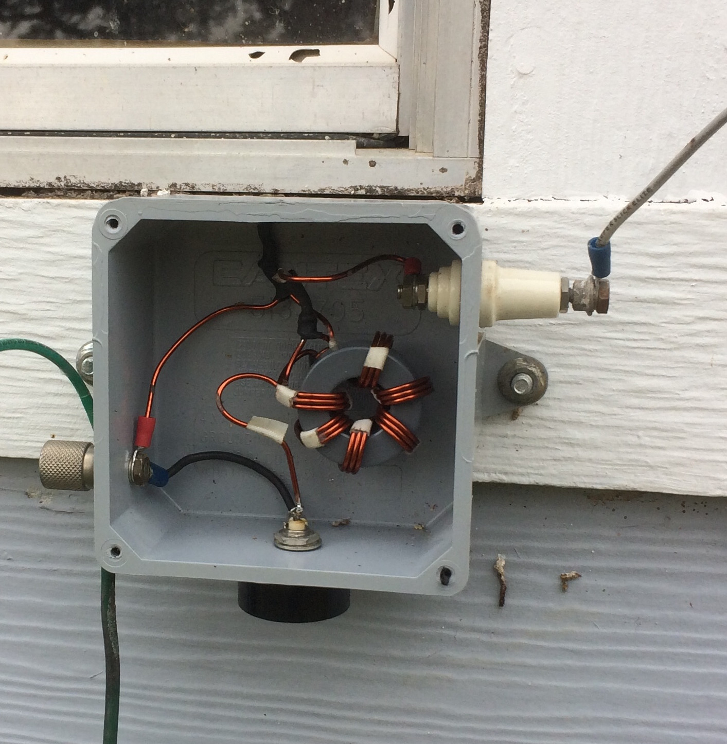
And here is the wired version with the "proof of concept " un-un to the left.  The box is an outdoor junction box (with water-sealed lid, not shown) that I picked up at a local big-box store.  Pretty handy.


And here it is as installed.  The BNC feed to the shack is at the bottom, the inverted "L" connects to the right and the ground and radials to the left.

So far, I am very pleased to get something cheap and easy working for 160M.  This might not be the best antenna, but for my circumstance it is up and working.   At 1810KHz, the antenna presents a SWR of about 1:1.1, rising quickly away from that QRP frequency.

I do appreciate Mr. Sevick's work. 

Now for more radials!

cln - Nick
WB5BKL
Lake Buchanan


Tuesday, May 29, 2018

Fiberglass center support - 40M extended double Zepp

I do not recommend anything to anyone anymore.

Having said that, I am personally pleased with the fiberglass tubing products from Max-Gain Systems.

I wanted to replace the relatively short fiberglass over galvanized steel center support for my 40M extended double Zepp (edZ).  I had two goals:  make it higher and make it non-conductive - simplifying the routing of the ladder-line feed.  

The telescoping fiberglass mast from Max-Gain is very nicely made.  The clamps are well thought-out and the instructions are clear.  The problems I had were entirely my own.

The clamps are entirely non-conductive and have a clever over-center lever to hold the tubing in place.  My problem was similar to the old British motorcycle joke about fasteners in aluminum castings:

Stages of bolt tightening for the novice mechanic:
                                               Loose
                                               Snug
                                               Tight
                                               Very Tight
                                               Loose


I snapped one of the clamping bolts during extension of the third fiberglass tube - it had been tightened to the 5th stage above.  After that, I was much more cautious.


Within a month I discovered I was too cautious.  With the constant flexing in the wind, two of the sections had partially collapsed - you can see one just above the roof level in the image to the right.  The looped ladderline is a dead giveaway.  

My QTH is in an area with almost constant breezes (a good thing in the Texas hill country).  The mast has one clamping support (at the roof apex) and is guyed only by the 40M edZ itself.

This means the mast is free to move in the wind.  In strong winds (say around 45 mph), I have seen the top of the previous fiberglass mast bent to almost 45 degrees.  We have had wind gusts of over 65 mph during storms with no permanent damage - it waves around like a fishing rod.   But all this movement did allow the telescoping mast to creep downward, especially in the lower sections which bear the weight of the sections above plus the downward component of the tightened edZ wires. 

[I know I am taking a chance here with minimum guying - but I am willing to bear that risk.  The previous fiberglass support was up for well over 12 years with no
apparent damage.]

I did not want to secure the sections with non-conductive pins. Sooner or later I would have to lower the mast and Max-Gain specifically warns against damaging the tubing finish as clearances are tight.  The same argument applies for any sort of clamp that would mar the tubing.


What I devised is shown to the left, just above the clamp mechanism.  It consists simply of three or four layers of electrical tape overlaid with a very tight tie-wrap (I have lots of tie-wraps, so I don't mind snapping one to get to stage 4, above).  Obviously I had noted that the tubing collapse halted when the electrical tape and tie-wrap holding the ladderline hit the clamp.  

Seems to work well.  I will post a follow-up report in a year or so.   


40M extended double Zepp details:

Orientation:                Roughly North-South
Center height:            about 46 feet
South end height:      about 25 feet (Live oak)
North end height:      about 30 feet (Pine)
Feed:                          450 Ohm ladder line


Best wishes to all.

cln - Nick
WB5BKL