For a little over a year, I have had an
intermittent problem with the K3. The problem occurred at boot-up
(power-on) and at least two error messages were consistently displayed: IO TST2
ERRPL1 Once these errors appeared, the radio was unusable.
I contacted Elecraft Support and
learned that these errors were most probably due to a connector
failure. The culprits seemed to be the connectors between the front
panel and the RF board. At Elecraft's suggestion, I purchased some
DeOxit and treated the connectors. My experience was similar to
other K3-owners on the Elecraft e-mail reflector – this fix only
lasted a few months.
As I was getting paranoid about
watching the display during boot, I decided to bite the bullet and
see about a better fix.
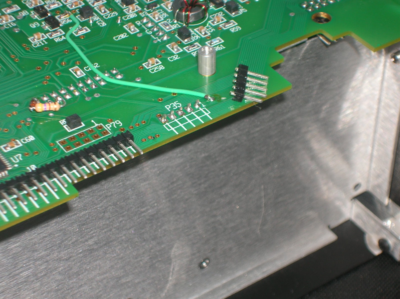
Elecraft support advised that the best
repair for this fault was to replace the original 28-pin P30 and
5-pin P35 tin-plated connectors with gold-plated ones and offered to
send me the parts (at no charge) or to arrange repair. Though I am
no longer a spring-chicken, I can still do through-hole soldering, so
I decided to try the repair.

Important Note: I am NOT
recommending you try this yourself. My advice is to return it to
Elecraft. Personally, I weighed the K3 time lost, shipping + repair
costs and probability of a botched job on my part and decided to give
it a shot.
Before every step, I made sure that
WB5BKL, the K3, tools and Earth were all at the same potential. I
had a binocular magnifier, excellent illumination, an anti-static mat
and a trusted soldering station available.
 First I pulled the front panel assembly
and then the bottom panel (I've gotten good at pulling the front
panel assembly over the past year). I elected to snip off the pins
as close to the plastic separator as possible. Then I carefully
heated the solder joint and pulled the remainder of the pin. I
later learned that it would might have been easier to remove the
plastic separators – and then pull the easier-to-grasp pins. Oh well.
First I pulled the front panel assembly
and then the bottom panel (I've gotten good at pulling the front
panel assembly over the past year). I elected to snip off the pins
as close to the plastic separator as possible. Then I carefully
heated the solder joint and pulled the remainder of the pin. I
later learned that it would might have been easier to remove the
plastic separators – and then pull the easier-to-grasp pins. Oh well.
Once all the pins were pulled, the most
tedious task remained – most of the holes were still filled with
solder. I used a fairly good solder-sucker I purchased at Frye's.
This one was spring-loaded and my biggest problem was making sure the
inlet was perfectly perpendicular to the RF board and heating
the joint and pushing the solder-sucker trigger at the same
time. Sort of like rubbing your stomach, patting your head and
whistling “The Eyes of Texas” simultaneously.
All but about 5 cleared immediately. I
spent quite a bit of time getting the final ones clear. I used a
pin off the old connector to check the holes for clearance. I was
afraid that if even one was tight, I might damage the new connector.
I was also thinking that the board was through-hole plated, so the
use of any force was probably a bad idea.

 Finally, they were clear. I did
several close inspections for solder bridges and then inserted the
new connectors.
Finally, they were clear. I did
several close inspections for solder bridges and then inserted the
new connectors.

Soldering them was relatively easy.
Another close inspection followed, revealing that I had missed one
pin on the 5-pin connector! Yikes! Another inspection followed –
and then one more. I checked the bottom of the board and touched up
a couple of pins where it appeared that I had been skimpy with the
solder.
 One more inspection and then it was
time for re-assembly.
One more inspection and then it was
time for re-assembly.
I admit to being apprehensive about the
first power-up, but everything seems to be working just fine.
Is it a permanent fix? I have no idea.
Ask me in a year or so.
WB5BKL – Nick


